Chapter 1 - System Overview
Chapter 5 - Liquefier Acquisition and Control Computer
Peripheral files
View website PDF document
Hi-res video: Building a helium recovery system (5 minutes long)
YouTube video: Building a helium recovery system (5 minutes long)
List of many parts with prices and links [xls]
Summary of Helium recovery system
Designed and built by Dr. Gregory S. Jenkins
University of Maryland at College Park
Department of Physics
Office: 301-405-0076
Manual last updated on 9/20/2016
 A
full laboratory helium recovery system has been implemented to mitigate the
burgeoning cost of liquid helium. Laboratory applications require cooling samples
and superconducting magnets down to temperatures below 2K, which requires
liquid helium.
A
full laboratory helium recovery system has been implemented to mitigate the
burgeoning cost of liquid helium. Laboratory applications require cooling samples
and superconducting magnets down to temperatures below 2K, which requires
liquid helium.
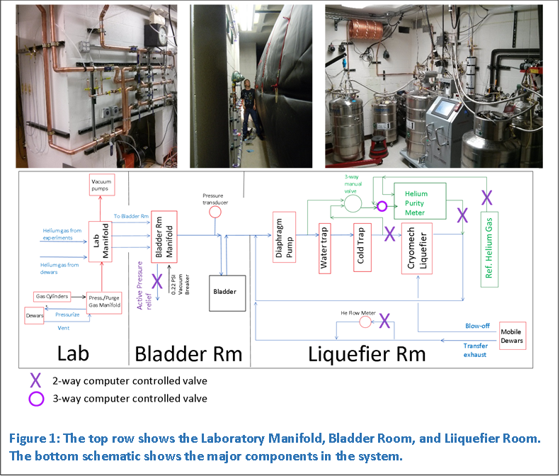
Figure 1 shows a simplified schematic of the main components of the system. The gas flow of the helium gas is indicated by the arrows. The laboratory applications vaporize liquid helium which is routed through a central laboratory manifold (Figure 1a). The manifold routes recovered helium gasses to the bladder room and allows flexibility of pumping and purging fore- and back lines. The bladder room manifold merges the three exhaust lines into one large line that interfaces with a 3600 cu. ft. helium recovery bladder (Figure 1b). The bladder acts as a ballast for the upstream helium flow.
A small diaphragm pump in the liquefier room draws the helium from the bladder and creates a 5 PSI pressure differential between the atmospheric helium in the bladder and the diaphragm pump output. The slightly pressurized gas is then purified by passing through a room temperature water trap and a liquid nitrogen cold trap. The purity of the gas is measured at automated intervals. A 99.99% purity level is required before the gas enters the Cryomech liquid helium plant 22 (LHeP22) liquefier. The gas is liquefied into a 150L dewar. The accumulated liquid helium is transferred out of the 150L dewar into mobile dewars. Some of the liquid is vaporized during the transfer and the exhaust is recaptured.
The mobile dewars are brought into the laboratory where the liquid is transferred to other cryostats used in experiments, and the helium is recaptured, and the process begins of helium recovery begins anew.
The above schematic omits details of the system like manual valves, safety relief and check valves, access ports, heaters, switches, computer acquisition and control, etc.. However, the schematic sets the stage to begin discussing the major components. The manual is organized into three mains sections: the Liquefier Room, the Bladder Room, and the Laboratory. The purpose and function of the subcomponents are discussed in each of these sections. The final section discusses the Liquefier Acqusition and Control Computer.
Next: Chapter 2 - Liquefier Room